Difference between revisions of "VPP/Segment Routing for IPv6"
m (Pcamaril moved page VPP/Segment Routing for IPv6: Overlay VPN with Underlay Optimization to VPP/Segment Routing for IPv6) |
VincentShi (Talk | contribs) m ("vpp sr steer" does not require the "sr policy" command to be declared after configuring "via".) |
||
| (6 intermediate revisions by 2 users not shown) | |||
| Line 7: | Line 7: | ||
== Introduction == | == Introduction == | ||
| − | Segment Routing changes the way packets are forwarded inside a network | + | Segment Routing changes the way packets are forwarded inside a network, enabling network operators to have better control on the path followed by the packets. In Segment Routing-enabled networks, packets are routed through sequence of segments, which are stored within the packet headers. The packets will always follow the shortest path up to each segment. In this way, no state is maintained in the network. |
| − | Segment Routing can be applied to the MPLS | + | Segment Routing can be applied to either the MPLS or the IPv6 dataplane. The IPv6 flavor of Segment Routing — a.k.a SRv6 — uses an IPv6 Routing Extension header, called ''Segment Routing header'' (SRH), where each segment is encoded as an IPv6 address. An ordered list of segments is thus encoded as an ordered list of IPv6 addresses in the SRH. The current ''active segment'' is the IPv6 ''Destination Address'' of the packet, while the next segment to be processed is indicated in the ''Segments Left'' field of the SRH. Upon completion of a segment, this field is updated to point to the next segment and the new ''active segment'' is copied in the ''Destination Address'' field of the IPv6 header. |
| − | + | On an SRv6-enabled node, the available segments are referred to as ''Local SIDs''. Each of them is associated with a processing function on the local node, which may range from advancing to the next SID in the SRH up to complex user-defined behaviors. | |
| − | In this example we will leverage SRv6 to create | + | In this example we will leverage SRv6 to create an L3VPN overlay for both IPv4 and IPv6 traffic, while also providing underlay optimization. |
| − | Note that | + | Note that SRv6 is not limited to this use-case. Please read the [https://docs.fd.io/vpp/17.07/srv6_doc.html doxygen documentation] for further information. |
== Topology Diagram == | == Topology Diagram == | ||
| Line 38: | Line 38: | ||
==== Configuration on C1 ==== | ==== Configuration on C1 ==== | ||
| − | set sr encaps source addr C1:: | + | vpp# set sr encaps source addr C1:: |
| − | sr policy add bsid C1::999:1 next C2:: next C4::6 encap | + | vpp# sr policy add bsid C1::999:1 next C2:: next C4::6 encap |
| − | sr steer l3 B::/112 via | + | vpp# sr steer l3 B::/112 via bsid C1::999:1 |
This configuration can be verified with the CLI: | This configuration can be verified with the CLI: | ||
| − | show sr policies | + | vpp# show sr pol |
| − | show sr steering policies | + | SR policies: |
| + | [0].- BSID: c1::999:1 | ||
| + | Behavior: Encapsulation | ||
| + | Type: Default | ||
| + | FIB table: 0 | ||
| + | Segment Lists: | ||
| + | [0].- < c2::, c4::6 > weight: 1 | ||
| + | ----------- | ||
| + | vpp# show sr steering policies | ||
| + | SR steering policies: | ||
| + | Traffic SR policy BSID | ||
| + | L3 b::/112 c1::999:1 | ||
==== Configuration on C2 ==== | ==== Configuration on C2 ==== | ||
| − | sr localsid address C2:: behavior end | + | vpp# sr localsid address C2:: behavior end |
This configuration can be verified with the CLI: | This configuration can be verified with the CLI: | ||
| − | show sr localsid | + | vpp# show sr localsid |
| + | SRv6 - My LocalSID Table: | ||
| + | ========================= | ||
| + | Address: c2:: | ||
| + | Behavior: End | ||
| + | Good traffic: [0 packets : 0 bytes] | ||
| + | Bad traffic: [0 packets : 0 bytes] | ||
| + | -------------------- | ||
Note that each SR LocalSID has counters for good and bad processed traffic. These counters can be cleared with | Note that each SR LocalSID has counters for good and bad processed traffic. These counters can be cleared with | ||
| − | clear sr localsid counters | + | vpp# clear sr localsid counters |
==== Configuration on C3 ==== | ==== Configuration on C3 ==== | ||
| − | + | ''None'' | |
==== Configuration on C4 ==== | ==== Configuration on C4 ==== | ||
| − | sr localsid address C4::6 behavior end.dx6 GigabitEthernet0/5/0 B:C5::B | + | vpp# sr localsid address C4::6 behavior end.dx6 GigabitEthernet0/5/0 B:C5::B |
| + | vpp# show sr localsid | ||
| + | SRv6 - My LocalSID Table: | ||
| + | ========================= | ||
| + | Address: c4::6 | ||
| + | Behavior: DX6 (Endpoint with decapsulation and IPv6 cross-connect) | ||
| + | Iface: GigabitEthernet0/5/0 | ||
| + | Next hop: b:c5::b | ||
| + | Good traffic: [6686 packets : 678832 bytes] | ||
| + | Bad traffic: [0 packets : 0 bytes] | ||
| + | -------------------- | ||
== L3VPN for IPv4 traffic == | == L3VPN for IPv4 traffic == | ||
| Line 80: | Line 108: | ||
==== Configuration on C1 ==== | ==== Configuration on C1 ==== | ||
| − | set sr encaps source addr C1:: | + | vpp# set sr encaps source addr C1:: |
| − | sr policy add bsid C1::999:2 next C2:: next C4::4 encap | + | vpp# sr policy add bsid C1::999:2 next C2:: next C4::4 encap |
| − | sr steer l3 2.2.2.0/24 via | + | vpp# sr steer l3 2.2.2.0/24 via bsid C1::999:2 |
==== Configuration on C2 ==== | ==== Configuration on C2 ==== | ||
| − | sr localsid address C2:: behavior end | + | vpp# sr localsid address C2:: behavior end |
Note here that this is the same SR LocalSID as the one created for the L3VPN for IPv6 traffic. Hence, you don't need to type this again. | Note here that this is the same SR LocalSID as the one created for the L3VPN for IPv6 traffic. Hence, you don't need to type this again. | ||
| Line 92: | Line 120: | ||
==== Configuration on C3 ==== | ==== Configuration on C3 ==== | ||
| − | + | ''None'' | |
==== Configuration on C4 ==== | ==== Configuration on C4 ==== | ||
| − | sr localsid address C4::4 behavior end.dx4 GigabitEthernet0/6/0 2.2.2.2 | + | vpp# sr localsid address C4::4 behavior end.dx4 GigabitEthernet0/6/0 2.2.2.2 |
| + | vpp# show sr localsid | ||
| + | SRv6 - My LocalSID Table: | ||
| + | ========================= | ||
| + | Address: c4::4 | ||
| + | Behavior: DX4 (Endpoint with decapsulation and IPv4 cross-connect) | ||
| + | Iface: GigabitEthernet0/6/0 | ||
| + | Next hop: 2.2.2.2 | ||
| + | Good traffic: [0 packets : 0 bytes] | ||
| + | Bad traffic: [0 packets : 0 bytes] | ||
| + | -------------------- | ||
Latest revision as of 08:55, 15 August 2023
VPP has an up-to-date implementation of SRv6 Network Programming.
This example shows how to use the VPP platform to setup a L3VPN with SRv6. For further information regarding the SRv6 implementation and CLI please visit the doxygen documentation. For further information on SRv6, tutorials and videos please visit www.segment-routing.net.
Contents
Introduction
Segment Routing changes the way packets are forwarded inside a network, enabling network operators to have better control on the path followed by the packets. In Segment Routing-enabled networks, packets are routed through sequence of segments, which are stored within the packet headers. The packets will always follow the shortest path up to each segment. In this way, no state is maintained in the network.
Segment Routing can be applied to either the MPLS or the IPv6 dataplane. The IPv6 flavor of Segment Routing — a.k.a SRv6 — uses an IPv6 Routing Extension header, called Segment Routing header (SRH), where each segment is encoded as an IPv6 address. An ordered list of segments is thus encoded as an ordered list of IPv6 addresses in the SRH. The current active segment is the IPv6 Destination Address of the packet, while the next segment to be processed is indicated in the Segments Left field of the SRH. Upon completion of a segment, this field is updated to point to the next segment and the new active segment is copied in the Destination Address field of the IPv6 header.
On an SRv6-enabled node, the available segments are referred to as Local SIDs. Each of them is associated with a processing function on the local node, which may range from advancing to the next SID in the SRH up to complex user-defined behaviors.
In this example we will leverage SRv6 to create an L3VPN overlay for both IPv4 and IPv6 traffic, while also providing underlay optimization.
Note that SRv6 is not limited to this use-case. Please read the doxygen documentation for further information.
Topology Diagram
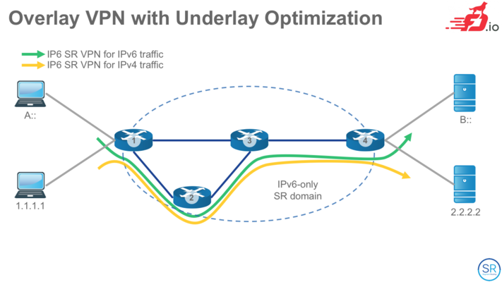
Our topology is simply going to be four VPP nodes with both, an IPv4 and IPv6 clients and servers attached to this core network. The 'core' network is running IPv6 only.
L3VPN for IPv6 traffic
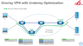
In this example what we will do is on C1 create a SR Policy with only one SID list. This SID list will be <C2::, C4::6>. The SR policy will be using encapsulation. On C1 I will add an steering policy to steer all the L3 traffic destined to B::/112 via the BindingSID of the SR policy we just created before.
On C2 I will create one SR LocalSID with behavior End. (Endpoint)
On C4 I will create one SR LocalSID with behavior End.DX6 (Endpoint with Decapsulation and IPv6 cross-connect).
Note that this is a L3VPN for all traffic from A:: to B::. In this example the returning path is not shown. The user must create another SR policy at C4 with the appropriate SR LocalSIDs at the different nodes for the returning path.
Configuration on C1
vpp# set sr encaps source addr C1::
vpp# sr policy add bsid C1::999:1 next C2:: next C4::6 encap
vpp# sr steer l3 B::/112 via bsid C1::999:1
This configuration can be verified with the CLI:
vpp# show sr pol
SR policies:
[0].-	BSID: c1::999:1
	Behavior: Encapsulation
	Type: Default
	FIB table: 0
	Segment Lists:
  	[0].- < c2::, c4::6 > weight: 1
-----------
vpp# show sr steering policies
SR steering policies:
Traffic		SR policy BSID
L3 b::/112	c1::999:1
Configuration on C2
vpp# sr localsid address C2:: behavior end
This configuration can be verified with the CLI:
vpp# show sr localsid
SRv6 - My LocalSID Table:
=========================
	Address: 	c2::
	Behavior: 	End
	Good traffic: 	[0 packets : 0 bytes]
	Bad traffic:  	[0 packets : 0 bytes]
--------------------
Note that each SR LocalSID has counters for good and bad processed traffic. These counters can be cleared with
vpp# clear sr localsid counters
Configuration on C3
None
Configuration on C4
vpp# sr localsid address C4::6 behavior end.dx6 GigabitEthernet0/5/0 B:C5::B
vpp# show sr localsid
SRv6 - My LocalSID Table:
=========================
	Address: 	c4::6
	Behavior: 	DX6 (Endpoint with decapsulation and IPv6 cross-connect)
	Iface:  	GigabitEthernet0/5/0
	Next hop: 	b:c5::b
	Good traffic: 	[6686 packets : 678832 bytes]
	Bad traffic:  	[0 packets : 0 bytes]
--------------------
L3VPN for IPv4 traffic
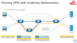
In this example what we will do is on C1 create a SR Policy with only one SID list. This SID list will be <C2::, C4::4>. The SR policy will be using encapsulation. On C1 I will add an steering policy to steer all the L3 traffic destined to 2.2.2.0/24 via the BindingSID of the SR policy we just created before.
On C2 I will create one SR LocalSID with behavior End. (Endpoint)
On C4 I will create one SR LocalSID with behavior End.DX4 (Endpoint with Decapsulation and IPv4 cross-connect).
Note that this is a L3VPN for all traffic from 1.1.1.0/24 to 2.2.2.0/24. In this example the returning path is not shown. The user must create another SR policy at C4 with the appropriate SR LocalSIDs at the different nodes for the returning path.
Configuration on C1
vpp# set sr encaps source addr C1::
vpp# sr policy add bsid C1::999:2 next C2:: next C4::4 encap
vpp# sr steer l3 2.2.2.0/24 via bsid C1::999:2
Configuration on C2
vpp# sr localsid address C2:: behavior end
Note here that this is the same SR LocalSID as the one created for the L3VPN for IPv6 traffic. Hence, you don't need to type this again.
Configuration on C3
None
Configuration on C4
vpp# sr localsid address C4::4 behavior end.dx4 GigabitEthernet0/6/0 2.2.2.2
vpp# show sr localsid
SRv6 - My LocalSID Table:
=========================
	Address: 	c4::4
	Behavior: 	DX4 (Endpoint with decapsulation and IPv4 cross-connect)
	Iface:  	GigabitEthernet0/6/0
	Next hop: 	2.2.2.2
	Good traffic: 	[0 packets : 0 bytes]
	Bad traffic:  	[0 packets : 0 bytes]
--------------------


